Hollow Shafts
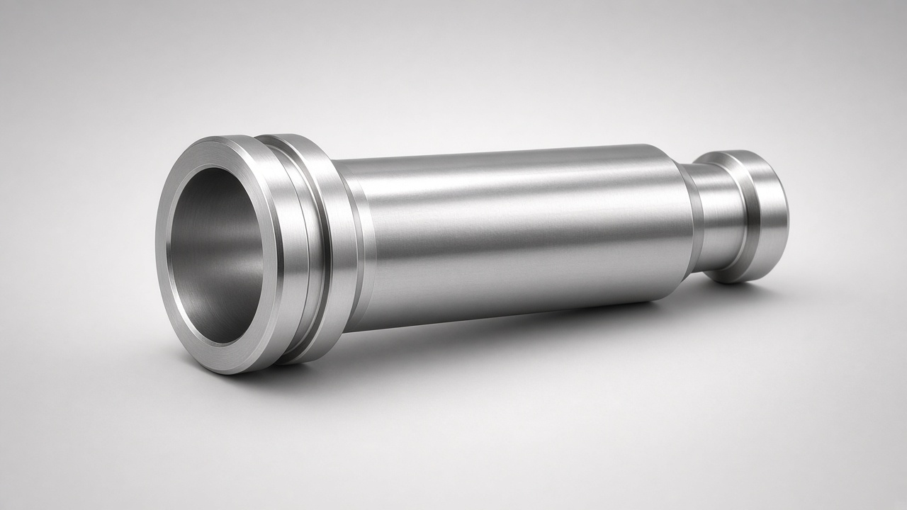
Tubular and bored shafts that cut weight, carry fluids or wiring, or accept nested drive elements. We machine OD, ID, and ends to fit bearings, seals, and couplings for robotics, spindles, and lightweight power-train designs.
Overview
Through-bore or stepped internal profiles
OD and ID concentricity for smooth rotation
Weight reduction without sacrificing journals
Passages for wiring, coolant, or hydraulics
Practical wall thickness for mid-size CNC shops
Hollow Shaft Specifications
Geometry
- • OD: Ø12–Ø150 mm typical
- • ID: Ø6–Ø120 mm depending on wall
- • Length: up to ~600–800 mm
- • Stepped or straight bore
- • Ends: threads, flanges, or keyways
Accuracy
- • OD tolerance ±0.01–0.02 mm
- • ID tolerance ±0.02 mm typical
- • Concentricity target 0.02–0.05 mm
- • Journal grind on request
- • Wall thickness check on report
Materials
- • Seamless tube or solid then bore
- • 1045 / 4140 / stainless 304–316
- • 6061 / 7075 aluminum tube
- • Stress relieve before finish turn
- • Coatings: anodize, black oxide, zinc
Common Applications
Motion Systems
- • Robot arm and joint shafts
- • Hollow spindle adapters
- • Cable-through servo shafts
- • Lightweight conveyor drives
- • Rotary unions and interfaces
Fluid & Process
- • Coolant or oil passages
- • Pump hollow drives
- • Pneumatic rotary feeds
- • Mixers with internal channels
- • Custom OEM hollow axles
Hollow Shaft Manufacturing Capabilities
Boring, turning, and finishing for tubular shafts that mid and small CNC shops need for weight and routing without specialty forge tooling.
Boring & Turning
Deep Boring / Gun Drill
OD Turning & Journals
Quality
Dimensional Control
Design & Engineering Services
Expert engineering support for your shaft requirements
Bore & Wall Design
- • Minimum wall for torque
- • Tube vs solid-then-bore choice
- • Stress-relieve planning
- • Seal gland and bearing layout
- • Balance recommendations
Machining Strategy
- • Gun drill / boring sequence
- • OD finish after heat treat
- • Support for thin walls
- • Inspection of ID and runout
- • Prototype quantity planning
Related Shaft Solutions
Custom Shaft
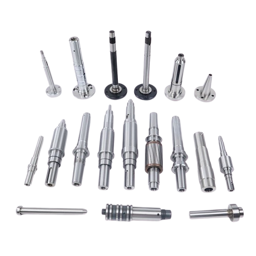
Tailored to exact client specifications with precision engineering and advanced design capabilities. Our custom shafts are engineered to meet your unique application requirements, featuring complex geometries, custom materials, and tight tolerances for optimal performance in specialized equipment and high-performance systems.
Forged Shafts
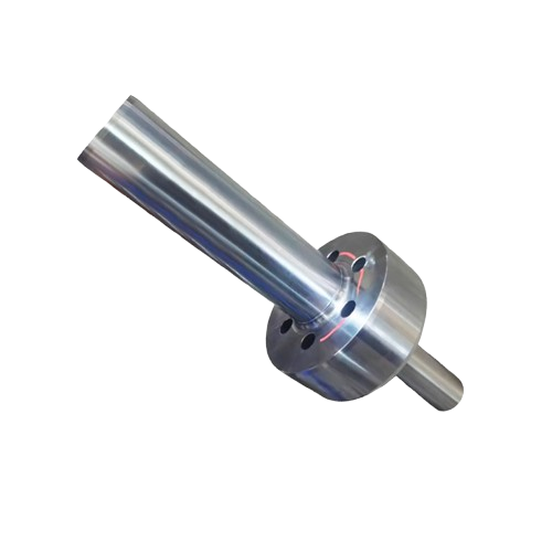
Enhanced material structure through advanced forging techniques for superior strength and durability. Our forged shafts feature improved grain structure, enhanced tensile strength, and exceptional fatigue resistance, making them ideal for heavy-duty applications in construction equipment, mining machinery, and power generation systems.
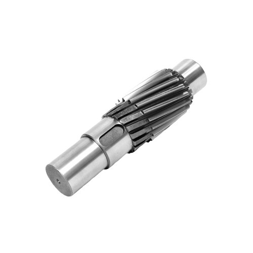
Gear Shafts
Expertly designed for seamless gear system integration with precision engineering for optimal performance. Our gear shafts feature custom gear profiles, precision tooth geometry, and advanced surface treatments, ensuring consistent quality and reliable operation in automotive transmission systems, industrial gearboxes, and power transmission applications.
Frequently Asked Questions
When should I use a hollow shaft?
Use a hollow shaft when you need lower rotating mass, a path for wires or fluid, or a nest for another shaft. It is common in robotics, spindles, and servo packages.
How thin can the wall be?
It depends on torque, length, and material. For steel in mid-size work we often keep walls practical for stable machining—send loads and we will recommend a safe minimum.
Do you start from tube or solid bar?
Both. Seamless tube is efficient for long straights; solid bar then bore suits stepped IDs or when tube stock is unavailable in the grade you need.
Can OD and ID be ground?
Yes. Critical journals can be ground after heat treat; ID honing or grind is available when seal or bearing fits demand it.
What lead times should I plan?
Prototypes often 2–3 weeks; production with heat treat and grind 3–6 weeks. Complex deep bores may add time for process trials.
Need Hollow or Bored Shafts?
Share OD, ID, length, and journal requirements. We will propose a boring and turning plan that keeps wall thickness and concentricity under control.